
If you’ve never had experience wiring a GFCI outlet (Ground Fault Circuit Interrupter) then keep reading. In my day we simply called these GFI outlets or GFIs. These devices precisely monitor the balance of electrical current moving through a circuit and immediately cut off the electricity when a short occurs. For more on the basics of a GFCI see our article on What is a GFCI. Note that these differ from Arc Fault Circuit Breakers, which work for slower losses of energy that tend to heat up wiring inside a home over time.
Wiring a GFCI outlet may vary slightly from manufacturer to manufacturer, but for the most part, they follow the same general principles. We asked our Pros to help us show new hires or even DIYers how to do it properly. You should understand the basics of how to correctly add a new GFCI outlet or replace an existing outlet with a GFCI.
What is a Ground Fault?
A “ground fault” represents any electric path between a source of current and a grounded surface. A ground fault occurs when current is “leaking” and escaping to the ground. How this occurs is significant. If your body provides a path to the ground for this leakage, you could be injured, burned, severely shocked, or electrocuted. Since water conducts electricity, ground faults are especially common in areas where water can provide a conduit for electricity to “escape” and find an alternate path to the ground.
Method 1: Simple Replacement of a Traditional Receptacle
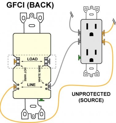
You can always replace a standard receptacle with a GFCI receptacle. You wiring it up exactly the same. This should go without saying but always cut power to the circuit (and verify with a circuit tester) before replacing an outlet. As shown below, you simply wire the ground connection and then connect both the hot and neutral wires to the GFCI’s LINE terminals as indicated to complete the replacement.
Breakdown of Installation Steps for Wiring a GFCI Outlet:
- Turn off the breaker at the panel which controls the circuit you are working on. If the circuit breakers aren’t labeled, you can find the right one by plugging a light or clock radio into the receptacle you are updating. Then, you simply turn off the breakers one by one until the light or radio goes off. It helps to have an assistant and cell phones during this phase. Once you turn off the correct breaker, mark it with tape to make sure a “helpful” person doesn’t accidentally flip it back on while you’re still working.
- Test the outlet with a circuit tester to verify that the power is indeed off (there’s nothing worse than finding out the hard way).
- Remove the receptacle’s cover plate and the screws holding the outlet in place and unscrew/disconnect the wires from the outlet.
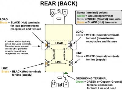
- Re-strip and re-connect the power-supply wires to the terminals marked “LINE”. Remember, the White wire connects to the Silver LINE screw and the Black wire connects to the Brass LINE screw. Connect the bare ground wire to the green (Ground) screw. (See Diagram A).
- Replace the receptacle, screw it back into the box, and attach the cover plate.
- Turn the power back on at the circuit-breaker panel.
- Plug a clock radio or light into the outlet.
- Test the GFCI by pressing the Black “Test” button on the outlet. If the radio turns off, the outlet is working.
- Reset the GFCI by pressing the “Reset” button on the outlet until it clicks into place. The clock radio or light should come back on.
Note: Some outlets will enable you to simply strip the ends of the wire and insert it into the push-in holes on the back of the receptacle. Electrician’s call this “backstabbing”. We don’t recommend this as it delivers a much lower quality bond to the wire. Over time, it can loosen and cause an arc fault. Use the terminal screws for the best possible connection.
Method 2: Replacement of a Traditional Receptacle and Downstream Circuit Protection
When you replace a standard receptacle with a GFCI, you can also protect any outlets or fixtures which exist downstream from the GFCI. To do this, you’ll need to use the LOAD terminals on the GFCI. These are typically covered by a yellow sticker.
Specific Installation Steps for Wiring a GFCI Outlet:
- Follow steps 1 through 3 above
- At this point when wiring a GFCI outlet, you’ll need to note which wires are the power supply “LINE” wires and which are the downstream “LOAD” wires. (These allow the GFCI to work as intended and protect all the outlets on the “LOAD” side.) To do this, make certain the wires are completely separate from one another (and not touching any ground) then turn the circuit breaker back on in the panel box.
- Use a circuit tester to determine which set of wires is “hot” (the “LINE” wires).
- Turn the power back off and re-tape the breaker in the panel box to avoid accident re-activation.
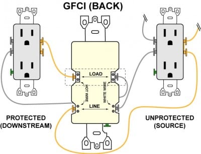
- Re-strip and connect the power supply wires to the terminals marked “LINE” and the downstream wires to the terminals marked “LOAD”. Remember, White wires connect to Silver screws and Black wires connect to Brass Screws. Connect the bare ground wire(s) to the green (Ground) screw. (See Diagram B).
- Replace the receptacle, screw it back into the box and attach the cover plate.
- Turn the power back on at the circuit breaker panel.
- Plug a clock radio or light into the outlet.
- Test the GFCI by pressing the Black “Test” button on the outlet. If the clock radio or light turns off, the outlet is working.
- Reset the GFCI by pressing the Red “Reset” button on the outlet until it clicks into place. The clock radio or light should come back on.
Wrapping It Up
Ground Fault Circuit Interrupters are critical in any home. Wiring a GFCI outlet into your home helps you bring older houses up to code. In general, however, you should want to add these outlets where needed. It’s an inexpensive task that can add a level of safety to your home and family.
Be sure to understand exactly how to wire downstream GFCI circuits as well (this means understanding the LOAD function). In this way, you can protect entire areas without having to replace every individual receptacle with expensive GFCI outlets.
